link AVIONICS

Interested in Avionics, Visit, http://avionics0.blogspot.com

Monday, February 14, 2011

Wingtip device


Wingtip devices are usually intended to improve the efficiency of fixed-wing aircraft. There are several types of wingtip devices, and though they function in different manners, the intended effect is always to reduce the aircraft's drag by altering the airflow near the wingtips. Wingtip devices can also improve aircraft handling characteristics and enhance safety for following aircraft. Such devices increase the effective aspect ratio of a wing without materially increasing the wingspan. An extension of span would lower lift-induced drag, but would increase parasitic drag and would require boosting the strength and weight of the wing. At some point, there is no net benefit from further increased span. There may also be operational considerations that limit the allowable wingspan (e.g., available width at airport gates).
Wingtip devices increase the lift generated at the wingtip (by smoothing the airflow across the upper wing near the tip) and reduce the lift-induced drag caused by wingtip vortices, improving lift-to-drag ratio. This increases fuel efficiency in powered aircraft and increases cross-country speed in gliders, in both cases increasing range.

Winglets are employed on many aircraft types, such as:
  • Rutan VariEze, the first aircraft to use winglets (1975)
  • Learjet 28/29, the first production jet aircraft to use winglets (1977)
  • Glaser-Dirks DG-303, an early glider derivative design, incorporating winglets as factory standard equipment
  • Airbus A310-300, the first airliner to feature wingtip fences (1985)
  • Boeing 747-400, the first mainline airliner to feature winglets (1988)
  • Ilyushin Il-96, first Russian and modern jet to feature winglets (1988)
  • Tupolev Tu-204, first narrow body aircraft to feature winglets (1994)


Monday, December 27, 2010

Lightning detection

A lightning detector is a device that detects lightning produced by thunderstorms. There are three primary types of detectors: ground-based systems using multiple antennas, mobile systems using a direction and a sense antenna in the same location (often aboard an aircraft), and space-based systems.


For more http://avionics0.blogspot.com/2010/12/lightning-detection.html

Saturday, November 13, 2010

Flaps

Flaps are hinged surfaces on the trailing edge of the wings of a fixed-wing aircraft. As flaps are extended, the stalling speed of the aircraft is reduced, which means that the aircraft can fly safely at slower speeds (especially during take off and landing). Flaps are also used on the leading edge of the wings of some high-speed jet aircraft, where they may be called Krueger flaps.
Extending flaps increases the camber of the wing airfoil, thus raising the maximum lift coefficient. This increase in maximum lift coefficient allows the aircraft to generate a given amount of lift with a slower speed. Therefore, extending the flaps reduces the stalling speed of the aircraft
Extending flaps also increases drag. This can be beneficial in the approach and landing phase because it helps to slow the aircraft. Another useful side effect of flap deployment is a decrease in aircraft pitch angle. This provides the pilot with a greater view over the nose of the aircraft and allows a better view of the runway during approach and landing.
Some trailing edge flap systems increase the planform area of the wing in addition to changing the camber. In turn, the larger lifting surface allows the aircraft to generate a given amount of lift with a slower speed, thus further reducing stalling speed. Although this effect is very similar to increasing the lift coefficient, raising the planform area of the wing does not itself raise the lift coefficient. The Fowler flap is an example of a flap system that increases the planform area of the wing in addition to increasing the camber.


Triple-slotted trailing-edge flaps and leading edge Krueger (unslotted and slotted) flaps fully extended on a Boeing 747 for landing.


Types of flap systems include:
  • Krueger flap: hinged flap on the leading edge. Often called a "droop".
  • Plain flap: rotates on a simple hinge.
  • Split flap: upper and lower surfaces are separate, the lower surface operates like a plain flap, but the upper surface stays immobile or moves only slightly.
  • Gouge flap: a cylindrical or conical aerofoil section which rotates backwards and downwards about an imaginary axis below the wing, increasing wing area and chord without affecting trim. Invented by Arthur Gouge for Short Brothers in 1936.
  • Fowler flap: slides backwards before hinging downwards, thereby increasing both camber and chord, creating a larger wing surface better tuned for lower speeds. It also provides some slot effect. The Fowler flap was invented by Harlan D. Fowler.
  • Fairey-Youngman flap: moves body down before moving aft and rotating.
  • Slotted flap: a slot (or gap) between the flap and the wing enables high pressure air from below the wing to re-energize the boundary layer over the flap. This helps the airflow to stay attached to the flap, delaying the stall.
  • Blown flaps: systems that blow engine air over the upper surface of the flap at certain angles to improve lift characteristics.

Friday, November 12, 2010

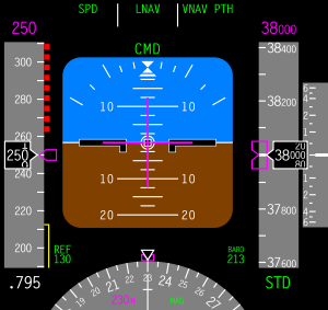
Primary Flight Display (PFD)


A primary flight display or PFD is a modern aircraft instrument dedicated to flight information. Much like multi-function displays, primary flight displays are built around an LCD or CRT display device. Representations of older six pack or "steam gauge" instruments are combined on one compact display, simplifying pilot workflow and streamlining cockpit layouts.


For more  http://avionics0.blogspot.com/2010/11/primary-flight-display-pfd.html

Thursday, October 21, 2010

Thermal Anti-Icing System

Thermal systems used for the purpose of preventing the formation of ice or for deicing airfoil leading edges, usually use heated air ducted spanwise along the inside of the leading edge of the airfoil and distributed around its inner surface. However, electrically heated elements are also used for anti-icing and deicing airfoil leading edges.
There are several methods used to provide heated air. These include bleeding hot air from the turbine
compressor, engine exhaust heat exchangers, and ram air heated by a combustion heater.

Anti-Icing Using Cotibustion Heaters
Anti-icing systems using combustion heaters usually have a separate system for each wing and the empennage. A typical system of this type has the required number of combustion heaters located in each wing and in the empennage. A system of ducting and valves controls the airflow. The anti-icing system is automatically controlled by overheat switches, thermal cycling switches, a balance control, and a duct pressure safety switch The overheat and cycling switches allow the heaters to operate at periodic intervals, and they also stop
heater operation completely if overheating occurs.

Anti-Icing Using Exhaust Heaters
Anti-icing of the wing and tail leading edges is accomplished by a controlled flow of heated air from heat muffs around a reciprocating engine’s tail pipe. In some installations this assembly is called an augmentor.
Normally, heated air from either engine supplies the wing leading edge anti-icing system in the same wing section. During single engine operation, a crossover duct system interconnects the left and right wing leading edge ducts. This duct supplies heated air to the wing section normally supplied by the inoperative engine. Check valves in the crossover duct prevent the reverse flow of heated air and also prevent cold air from entering the anti-icing system from the inoperative engine.

Anti Icing using Engine Bleed Air
Heated air for anti.icing is obtained by bleeding air from the engine compressor. The reason for the use of such a system is that relatively large amounts of very hot air can be tapped off the compressor, providing a satisfactory source of anti-icing and deicing heat.
The shut off valve for each anti-icing section is a pressure regulating type. The valve controls the flow of air from the bleed air system to the ejectors, where it is ejected through small nozzles into mixing chambers. The hot bleed air is mixed with ambient air.

Monday, October 11, 2010

Cabin Pressurization

Cabin pressurization is the active pumping of compressed air into an aircraft cabin when flying at altitude to maintain a safe and comfortable environment for crew and passengers in the low outside atmospheric pressure.
Pressurization is essential over 3,000 metres (9,800 ft) above sea level to protect crew and passengers from the risk of hypoxia and a number of other physiological problems in the thin air above that altitude and increases passenger comfort generally. "The outflow valve is constantly being positioned to maintain cabin pressure as close to sea level as practical, without exceeding a cabin-to-outside pressure differential of 8.60 psi."
Maintaining the cabin pressure altitude to below 3,000 metres (9,800 ft) generally avoids significant hypoxia, altitude sickness, decompression sickness and barotrauma. Emergency oxygen systems are installed, both for passengers and cockpit crew, to prevent loss of consciousness in the event that cabin pressure rapidly rises above 10,000 feet MSL. Those systems contain more than enough oxygen for all on board, to give the pilot adequate time to descend the plane to a safe altitude, where supplemental oxygen is not needed. Federal Aviation Administration (FAA) regulations in the U.S. mandate that the cabin altitude may not exceed 8,000 feet at the maximum operating altitude of the airplane under normal operating conditions.
The pressure maintained within the cabin is referred to as the equivalent effective cabin altitude or more normally, the "cabin altitude". Cabin altitude is not normally maintained at average mean sea level (MSL) pressure (1013.25 hPa, or 29.921 inches of mercury) throughout the flight, because doing so would cause the designed differential pressure limits of the fuselage to be exceeded. An aircraft planning to cruise at 40,000 ft (12,000 m) is programmed to rise gradually from take-off to around 8,000 ft (2,400 m) in cabin pressure altitude, and to then reduce gently to match the ambient air pressure of the destination.
Pressurization is achieved by the design of an airtight fuselage engineered to be pressurized with a source of compressed air and controlled by an environmental control system (ECS). The most common source of compressed air for pressurization is bleed air extracted from the compressor stage of a gas turbine engine, from a "low" or "intermediate" stage and also from an additional "high" stage. "The exact stage can vary, depending on engine type." By the time the cold outside air has reached the bleed air valves, it has been heated to around 200 °C (392 °F) and is at a very high pressure. The control and selection of high or low bleed sources is fully automatic and is governed by the needs of various pneumatic systems at various stages of flight.
The part of the bleed air that is directed to the ECS, is then expanded and cooled to a suitable temperature by passing it through a heat exchanger and air cycle machine ('the packs system'). In some of the larger airliners, hot trim air can be added downstream of air conditioned air coming from the packs, if it is needed to warm a section of the cabin that is colder than other sections
All exhaust air is dumped to atmosphere via an outflow valve, usually at the rear of the fuselage. This valve controls the cabin pressure and also acts as a safety relief valve, in addition to other safety relief valves. In the event that the automatic pressure controllers fail, the pilot can manually control the cabin pressure valve, according to the backup emergency procedure checklist. The automatic controller normally maintains the proper cabin pressure altitude by constantly adjusting the outflow valve position, so that the cabin pressure is as near to sea level pressure as practical, without exceeding the maximum differential limit of 8.60 psi. At 39,000 feet, the cabin pressure would be automatically maintained at about 6,900 feet (450 feet lower than Mexico City), which is about 11.5 psi of atmosphere pressure (76 kPa)