link AVIONICS

Interested in Avionics, Visit, http://avionics0.blogspot.com

Saturday, November 13, 2010

Flaps

Flaps are hinged surfaces on the trailing edge of the wings of a fixed-wing aircraft. As flaps are extended, the stalling speed of the aircraft is reduced, which means that the aircraft can fly safely at slower speeds (especially during take off and landing). Flaps are also used on the leading edge of the wings of some high-speed jet aircraft, where they may be called Krueger flaps.
Extending flaps increases the camber of the wing airfoil, thus raising the maximum lift coefficient. This increase in maximum lift coefficient allows the aircraft to generate a given amount of lift with a slower speed. Therefore, extending the flaps reduces the stalling speed of the aircraft
Extending flaps also increases drag. This can be beneficial in the approach and landing phase because it helps to slow the aircraft. Another useful side effect of flap deployment is a decrease in aircraft pitch angle. This provides the pilot with a greater view over the nose of the aircraft and allows a better view of the runway during approach and landing.
Some trailing edge flap systems increase the planform area of the wing in addition to changing the camber. In turn, the larger lifting surface allows the aircraft to generate a given amount of lift with a slower speed, thus further reducing stalling speed. Although this effect is very similar to increasing the lift coefficient, raising the planform area of the wing does not itself raise the lift coefficient. The Fowler flap is an example of a flap system that increases the planform area of the wing in addition to increasing the camber.


Triple-slotted trailing-edge flaps and leading edge Krueger (unslotted and slotted) flaps fully extended on a Boeing 747 for landing.


Types of flap systems include:
  • Krueger flap: hinged flap on the leading edge. Often called a "droop".
  • Plain flap: rotates on a simple hinge.
  • Split flap: upper and lower surfaces are separate, the lower surface operates like a plain flap, but the upper surface stays immobile or moves only slightly.
  • Gouge flap: a cylindrical or conical aerofoil section which rotates backwards and downwards about an imaginary axis below the wing, increasing wing area and chord without affecting trim. Invented by Arthur Gouge for Short Brothers in 1936.
  • Fowler flap: slides backwards before hinging downwards, thereby increasing both camber and chord, creating a larger wing surface better tuned for lower speeds. It also provides some slot effect. The Fowler flap was invented by Harlan D. Fowler.
  • Fairey-Youngman flap: moves body down before moving aft and rotating.
  • Slotted flap: a slot (or gap) between the flap and the wing enables high pressure air from below the wing to re-energize the boundary layer over the flap. This helps the airflow to stay attached to the flap, delaying the stall.
  • Blown flaps: systems that blow engine air over the upper surface of the flap at certain angles to improve lift characteristics.

Friday, November 12, 2010

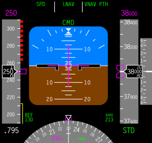
Primary Flight Display (PFD)


A primary flight display or PFD is a modern aircraft instrument dedicated to flight information. Much like multi-function displays, primary flight displays are built around an LCD or CRT display device. Representations of older six pack or "steam gauge" instruments are combined on one compact display, simplifying pilot workflow and streamlining cockpit layouts.


For more  http://avionics0.blogspot.com/2010/11/primary-flight-display-pfd.html

Thursday, October 21, 2010

Thermal Anti-Icing System

Thermal systems used for the purpose of preventing the formation of ice or for deicing airfoil leading edges, usually use heated air ducted spanwise along the inside of the leading edge of the airfoil and distributed around its inner surface. However, electrically heated elements are also used for anti-icing and deicing airfoil leading edges.
There are several methods used to provide heated air. These include bleeding hot air from the turbine
compressor, engine exhaust heat exchangers, and ram air heated by a combustion heater.

Anti-Icing Using Cotibustion Heaters
Anti-icing systems using combustion heaters usually have a separate system for each wing and the empennage. A typical system of this type has the required number of combustion heaters located in each wing and in the empennage. A system of ducting and valves controls the airflow. The anti-icing system is automatically controlled by overheat switches, thermal cycling switches, a balance control, and a duct pressure safety switch The overheat and cycling switches allow the heaters to operate at periodic intervals, and they also stop
heater operation completely if overheating occurs.

Anti-Icing Using Exhaust Heaters
Anti-icing of the wing and tail leading edges is accomplished by a controlled flow of heated air from heat muffs around a reciprocating engine’s tail pipe. In some installations this assembly is called an augmentor.
Normally, heated air from either engine supplies the wing leading edge anti-icing system in the same wing section. During single engine operation, a crossover duct system interconnects the left and right wing leading edge ducts. This duct supplies heated air to the wing section normally supplied by the inoperative engine. Check valves in the crossover duct prevent the reverse flow of heated air and also prevent cold air from entering the anti-icing system from the inoperative engine.

Anti Icing using Engine Bleed Air
Heated air for anti.icing is obtained by bleeding air from the engine compressor. The reason for the use of such a system is that relatively large amounts of very hot air can be tapped off the compressor, providing a satisfactory source of anti-icing and deicing heat.
The shut off valve for each anti-icing section is a pressure regulating type. The valve controls the flow of air from the bleed air system to the ejectors, where it is ejected through small nozzles into mixing chambers. The hot bleed air is mixed with ambient air.

Monday, October 11, 2010

Cabin Pressurization

Cabin pressurization is the active pumping of compressed air into an aircraft cabin when flying at altitude to maintain a safe and comfortable environment for crew and passengers in the low outside atmospheric pressure.
Pressurization is essential over 3,000 metres (9,800 ft) above sea level to protect crew and passengers from the risk of hypoxia and a number of other physiological problems in the thin air above that altitude and increases passenger comfort generally. "The outflow valve is constantly being positioned to maintain cabin pressure as close to sea level as practical, without exceeding a cabin-to-outside pressure differential of 8.60 psi."
Maintaining the cabin pressure altitude to below 3,000 metres (9,800 ft) generally avoids significant hypoxia, altitude sickness, decompression sickness and barotrauma. Emergency oxygen systems are installed, both for passengers and cockpit crew, to prevent loss of consciousness in the event that cabin pressure rapidly rises above 10,000 feet MSL. Those systems contain more than enough oxygen for all on board, to give the pilot adequate time to descend the plane to a safe altitude, where supplemental oxygen is not needed. Federal Aviation Administration (FAA) regulations in the U.S. mandate that the cabin altitude may not exceed 8,000 feet at the maximum operating altitude of the airplane under normal operating conditions.
The pressure maintained within the cabin is referred to as the equivalent effective cabin altitude or more normally, the "cabin altitude". Cabin altitude is not normally maintained at average mean sea level (MSL) pressure (1013.25 hPa, or 29.921 inches of mercury) throughout the flight, because doing so would cause the designed differential pressure limits of the fuselage to be exceeded. An aircraft planning to cruise at 40,000 ft (12,000 m) is programmed to rise gradually from take-off to around 8,000 ft (2,400 m) in cabin pressure altitude, and to then reduce gently to match the ambient air pressure of the destination.
Pressurization is achieved by the design of an airtight fuselage engineered to be pressurized with a source of compressed air and controlled by an environmental control system (ECS). The most common source of compressed air for pressurization is bleed air extracted from the compressor stage of a gas turbine engine, from a "low" or "intermediate" stage and also from an additional "high" stage. "The exact stage can vary, depending on engine type." By the time the cold outside air has reached the bleed air valves, it has been heated to around 200 °C (392 °F) and is at a very high pressure. The control and selection of high or low bleed sources is fully automatic and is governed by the needs of various pneumatic systems at various stages of flight.
The part of the bleed air that is directed to the ECS, is then expanded and cooled to a suitable temperature by passing it through a heat exchanger and air cycle machine ('the packs system'). In some of the larger airliners, hot trim air can be added downstream of air conditioned air coming from the packs, if it is needed to warm a section of the cabin that is colder than other sections
All exhaust air is dumped to atmosphere via an outflow valve, usually at the rear of the fuselage. This valve controls the cabin pressure and also acts as a safety relief valve, in addition to other safety relief valves. In the event that the automatic pressure controllers fail, the pilot can manually control the cabin pressure valve, according to the backup emergency procedure checklist. The automatic controller normally maintains the proper cabin pressure altitude by constantly adjusting the outflow valve position, so that the cabin pressure is as near to sea level pressure as practical, without exceeding the maximum differential limit of 8.60 psi. At 39,000 feet, the cabin pressure would be automatically maintained at about 6,900 feet (450 feet lower than Mexico City), which is about 11.5 psi of atmosphere pressure (76 kPa)

Saturday, September 25, 2010

Environmental Control System (ECS)

The Environmental Control System of an airliner provides air supply, thermal control and cabin pressurization for the passengers and crew. Avionics cooling, smoke detection, and fire suppressionare also commonly considered part of the Environmental Control System.


On most jetliners, air is supplied to the ECS by being "bled" from a compressor stage of each gas turbine engine, upstream of the combustor. The temperature and pressure of this "bleed air" varies widely depending upon which compressor stage and the RPM of the engine.
A "Manifold Pressure Regulating Shut-Off Valve" (MPRSOV) restricts the flow as necessary to maintain the desired pressure for downstream systems. This flow restriction results in efficiency losses. To reduce the amount of restriction required, and thereby increase efficiency, air is commonly drawn from two bleed ports (3 on the Boeing 777).
When the engine is at low thrust, the air is drawn from the "High Pressure Bleed Port." As thrust is increased, the pressure from this port rises until "crossover," where the "High Pressure Shut-Off Valve" (HPSOV) closes and air is thereafter drawn from the "Low Pressure Bleed Port."
To achieve the desired temperature, the bleed-air is passed through a heat exchanger called a "pre-cooler." Air from the jet engine fan is blown across the pre-cooler, which is located in the engine strut. A "Fan Air Modulating Valve" (FAMV) varies the cooling airflow, and thereby controls the final air temperature of the bleed air.

The Cold Air Unit, or "Airconditioning pack" is usually an air cycle machine (ACM) cooling device. Some aircraft, including early 707 jetliners, used vapor-compression refrigeration like that used in home air conditioners.
On most jetliners, the A/C packs are located in the "Wing to Body Fairing" between the two wings beneath the fuselage. On some jetliners (Douglas Aircraft DC-9 Series) the A/C Packs are located in the tail. The A/C Packs on the McDonnell Douglas DC-10/MD-11 and LockheedL-1011 are located in the front of the aircraft beneath the flight deck. Nearly all jetliners have two packs, although larger aircraft such as the Boeing 747, Lockheed L-1011, and McDonnell-Douglas DC-10/MD-11 have three.
The quantity of bleed air flowing to the A/C Pack is regulated by the "Flow Control Valve" (FCV). One FCV is installed for each pack. A normally closed "isolation valve" prevents air from the left bleed system from reaching the right pack (and v.v.), although this valve may be opened in the event of loss of one bleed system.

The A/C Pack exhaust air is ducted into the pressurized fuselage, where it is mixed with filtered air from the recirculation fans, and fed into the "mix manifold". On nearly all modern jetliners, the airflow is approximately 50% "outside air" and 50% "filtered air."
Modern jetliners use "High Efficiency Particulate Arresting" HEPA filters, which trap >99% of all bacteria and clustered viruses.
Airflow into the fuselage is approximately constant, and pressure is maintained by varying the opening of the "Out Flow Valve" (OFV). Most modern jetliners have a single OFV located near the bottom aft end of the fuselage, although some larger aircraft like the 747 and 777 have two.
In the event the OFV should fail closed, at least two Positive Pressure Relief Valves (PPRV) and at least one Negative Pressure Relief Valve (NPRV) are provided to protect the fuselage from over- and under- pressurization.
The atmosphere at typical jetliner cruising altitudes is generally very dry and cold, and the outside air pumped into the cabin on a long flight typically has a relative humidity around 10%. The fact that cabin pressure is generally lower than the pressure at ground level does not of itself contribute to the dryness.


Thursday, September 16, 2010

AIRCRAFT MASS AND BALANCE

AIRCRAFT MASS AND BALANCE

The main purposes, of monitoring the mass and balance of aircraft, are to maintain safety and to achieve efficiency in flight. The position of loads such as passengers, fuel, cargo and equipment will alter the position of the Centre of Gravity (CG) of the aircraft.

Incorrect loading will affect the aircraft rate of climb, manoeuvrability, ceiling, speed and fuel consumption. If the CG were too far forward, it would result in a nose-heavy condition, which could be potentially dangerous on take-off and landing. If the CG is too far aft, the tail-heavy condition will increase the tendency of the aircraft to stall and make landing more difficult.

Stability of the aircraft will also be affected with the CG outside the normal operational limits. Provided the CG lies within specified limits, the aircraft should be safe to fly. The unit of measurement for mass and balance are normally dictated by the aircraft manufacturer and can be either Metric or Imperial terms. Specific definitions for mass and balance ensure they are correctly interpreted.

Datum: The datum is an imaginary vertical plane from which horizontal measurements are taken. The locations of items such as baggage compartments, fuel tanks, seats and engines are relevant to the datum. There is no fixed rule for the location of the datum. The manufacturer will normally specify the nose of the aircraft, but it could be at the front main bulkhead or even forward of the aircraft nose

Arm: The horizontal distance from an item or piece of equipment to the datum. The arm's distance is usually measured in inches (or millimetres) and may be preceded by a plus (+) or a minus (-) sign. The plus sign indicates that the distance is aft of the datum and the minus sign indicates distance is forward of the datum

Moment: The product of a force multiplied by the distance about which the force acts. In the case of mass and balance, the force is the mass (kg/lb) and the distance is the arm (m/in). Therefore, a mass of 40 kilograms, at 3 metres aft of the datum will have a moment of 40 x 3 = 120 kg/m. It is important to consider whether a value is positive (+ve) or negative (-ve) when moments are calculated and the following conventions are used:

Distances horizontal: aft of the datum (+), forward of the datum (-).
Weight: added (+), removed (-).

Centre of Gravity (CG): This is the point about which all of the mass of the aircraft or object is concentrated. An aircraft could be suspended from this point and it would not adopt a nose-down nor a tail-down attitude.

Centre of Gravity Balance Limits: For normal operation of the aircraft, the CG should be between the Forward and Aft limits as specified by the manufacturer. If the CG is outside these limits, the aircraft performance will be affected and the aircraft may be unsafe.

Dry Operating Mass: The total mass of the aeroplane, ready for a specific type of operation, excluding all usable fuel and traffic load. This mass includes crew and crew baggage, catering and removable passenger service equipment, potable water and lavatory chemicals.

Maximum Zero Fuel Mass: The maximum permissible mass of an aircraft with no usable fuel.  Fuel contained in certain tanks must be included if this is explicitly mentioned in the aircraft’s Flight Manual limitations.

Maximum Structural Take-Off Mass (MTOM): The maximum permissible total aeroplane mass at the start of the take-off run.

Maximum Structural Landing Mass: The maximum permissible total aeroplane mass upon landing under normal circumstances.

Traffic Load: This includes the total mass of passengers, baggage and cargo, including any non-revenue load.


Mass and Balance Documentation

The Mass and Balance documentation used by an operator must include certain basic information, which is listed below. Subject to the approval of the authority, some of this information may be omitted.

A. Aeroplane registration and type
B. Flight identification number and date
C. Identity of the commander
D. Identity of the person who prepared the document
E. Dry operating mass and the corresponding CG of the aeroplane
F. Mass of the fuel at take-off and the mass of trip fuel
G. Mass of consumables other than fuel
H. Load components that include passengers, baggage, freight and ballast
I. Take-off Mass, Landing Mass and Zero Fuel mass.
J. The load distribution
K. Aeroplane CG positions
L. Limiting mass and CG values


FREQUENCY OF WEIGHING

Aircraft must be weighed before entering service, to determine the individual mass and CG position. This should be done once all manufacturing processes have been completed. The aircraft must also be re-weighed within four years from the date of manufacture, if individual mass is used, or within nine years from the date of manufacture, if fleet masses are used.

The mass and CG position of an aircraft must be periodically re-established. The maximum interval between one aircraft weigh and the next, must be defined by the operator, but not exceed the four/nine year limits

15.7 CALCULATION OF MASS AND CG OF ANY SYSTEM

The position of the CG of any system (refer to Fig. 1) may be found using the following process:

Total Mass is calculated, by adding the mass of each load (plus the mass of the beam)

The moment of each load is calculated, by multiplying the mass by the arm (distance from the reference datum)

ALL the moments are added together, to provide the Total Moment

Total Moment is divided by the Total Mass to give CG position.

Saturday, September 4, 2010

Aviation Hydraulic Oil


Aircraft hydraulic fluids fall under various specifications:
Common petroleum-based:
  • Mil-H-5606: Mineral base, flammable, fairly low flashpoint, usable from −65 °F (−54 °C) to 275 °F (135 °C), red color
  • Mil-H-83282: Synthetic hydrocarbon base, higher flashpoint, self-extinguishing, backward compatible to -5606, red color, rated to −40 °F (−40 °C) degrees.
  • Mil-H-87257: A development of -83282 fluid to improve its low temperature viscosity.
Phosphate-ester based:
  • BMS 3-11: Skydrol 500B-4, Skydrol LD-4, Skydrol 5 and Exxon HyJetIV-A plus – Typically light purple, not compatible with petroleum-based fluids, will not support combustion.