Bleeding a Shock Strut
If the fluid level of a shock strut has becomeextremely low, or if for any other reason air is
trapped in the strut cylinder, it may be necessary to bleed the strut during the servicing operation. Bleeding is usually performed with the aircraft placed on jacks. In this position the shock struts can be extended and compressed during the filling operation, thus expelling all the entrapped air. The following is a typical bleeding procedure :
Construct a bleed hose containing a fitting suitable for making an airtight connection to the shock strut filler opening. The base should be long enough to reach from the when the aircraft is on jacks.
Jack the aircraft until all shock struts are fully extended.
Release the air pressure in the strut to bebled.
Remove the air valve assembly.
Fill the strut to the level of the filler port with an approved type hydraulic fluid.
Attach the bleed hose to the filler port and insert the free end of the hose into a container of clean hydraulic fluid, making sure that this end of the hose is below the surface of the hydraulic fluid.
Place an exerciser jack or other suitable single-base jack under the shock strut jacking point. Compress and
extend the strut fully by raising and lowering the jack until the flow of air bubbles from the strut has completely stopped.
Compress the strut slowly and allow it to extend by its own weight.
Remove the exerciser jack, and then lower and remove all other jacks.
Remove the bleed hose from the shock strut.
Install the air valve and inflate the strut
Friday, August 27, 2010
Landing Gear System

Undercarriage Configuration
1. Conventiol -Main wheel + tail wheel
2. Tricycle - Main wheel + nose wheel
3. Tandom. - Main wheel + out trigger wheels
Shock Struts
Shock struts are self-contained hydraulic units that support an aircraft on the ground and protect
the aircraft structure by absorbing and dissipating the tremendous shock loads of landing. Shock struts must be inspected and serviced regularly to function efficiently.
SHIMMY DAMPERS
A shimmy damper controls vibration, or shimmy, through hydraulic damping. The damper is either attached to or built integrally with the nose gear and prevents shimmy of the nosewheel during taxiing, landing, or takeoff. There are three types of shimmy dampers commonly used on aircraft:
(1)The piston type,
(2) vane type, and
(3) features incorporated in the nosewheel power steering system of some aircraft.
Steer Damper
A steer damper is hydraulically operaied and accomplishes the two separate functions of steering
and/or eliminating shimmying.
Thursday, August 19, 2010

Sunday, August 15, 2010
ICAO phonetic alphabet
ICAO phonetic alphabet :
A ALPHA AL fah
B BRAVO BRAH VO
C CHARLIE CHAR lee
D DELTA DELL tah
E ECHO ECK oh
F FOXTROT FOKS trot
G GOLF GOLF
H HOTEL hoh TELL
I INDIA IN dee ah
J JULIETT JEW lee ETT
K KILO KEY loh
L LIMA LEE mah
M MIKE MIKE
N NOVEMBER no VEM ber
O OSCAR OSS cah
P PAPA pah PAH
Q QUEBEC keh BECK
R ROMEO ROW me oh
S SIERRA see AIR ah
T TANGO TANG go
U UNIFORM YOU nee form
V VICTOR VIK tah
W WHISKEY WISS key
X X-RAY ECKS RAY
Y YANKEE YANG key
Z ZULU ZOO loo
Friday, August 13, 2010
GPWS (Ground Proximity Warning System)
GPWS (Ground Proximity Warning System)
A ground proximity warning system (GPWS) is a system designed to alert pilots if their aircraft is in immediate danger of flying into the ground or an obstacle.
More advanced systems, introduced in 1996, are known as enhanced ground proximity warning systems (EGPWS) .sometimes confusingly called terrain awareness warning systems.
For more information..
http://avionics0.blogspot.com/2010/08/gpws-ground-proximity-warning-system.html
Tuesday, August 10, 2010
Aircraft Avionics Systems
Full Categorized aircraft avionics equipment list,
http://avionics0.blogspot.com/p/avionics-in-aircraft.html
http://avionics0.blogspot.com/p/avionics-in-aircraft.html
Sunday, August 8, 2010
CFM and GE certify third engine in two weeks

For the third time in two weeks, CFM (GE & Snecma) and GE have announced certification of new engine variants. Most recently on July 30, CFM was granted certification of the updated CFM56-7BE engine, which will enter service in mid-2011 on the Boeing 737.
The -7BE evolution engine will fly in the fourth quarter on a Continental 737-800, as Boeing looks to deliver at least 2% improvement in fuel burn to its existing single-aisle product line. The company test flew the new nacelle design in August 2009.
The engine features a revised high pressure turbine guide vane diffuser, improved high pressure turbine blades, disc and a revised forward outer seal, along with improvements low pressure turbine blades, vanes, discs and case.
While CFM outwardly states that the engine will contribute 1% improvement on its own, testing has found that the engine will deliver 1.6% improvement in fuel burn. An additional 1% will come from aerodynamic refinements to the exterior of the 737.
The CFM56-7BE engine is part of a host of improvements to the 737, which also include the Boeing Sky Interior, which will enter service with flyDubai, the first of 37 customers later this year.
Wednesday, August 4, 2010
Aircraft Hydraulic Fluids
Aircraft hydraulic fluids fall under various specifications:
Common petroleum-based:
Common petroleum-based:
- Mil-H-5606: Mineral base, flammable, fairly low flashpoint, usable from −65 °F (−54 °C) to 275 °F (135 °C), red color
- Mil-H-83282: Synthetic hydrocarbon base, higher flashpoint, self-extinguishing, backward compatible to -5606, red color, rated to −40 °F (−40 °C) degrees.
- Mil-H-87257: A development of -83282 fluid to improve its low temperature viscosity.
Aircraft Ground Checks
Ground Checks
Before the pilot starts to carry out checks on the aircraft itself, it is important to check
the area around the aircraft. The pilot will be looking out for a number of things.
The position of the aircraft in relation to other things to ensure there is room to
manoeuvre the aircraft safely..
The area is free of rubbish and stones which could be picked-up by jet intakes or
propellers.
The aircraft has chocks in place (until parking brakes are on).
Fire extinguishers are readily available.
External Aircraft Checks
Many faults or potential problems can be discovered by carrying out visual checks on
the aircraft. Before flying the pilot will walk around the aircraft systematically to
ensure nothing is missed out. In addition to making an inspection of specific parts of
the aircraft, the pilot must look out for damage or wear on the 'skin', 'popped' rivets,
and leaking oil, fuel or hydraulic fluid. A typical walk round could be as follows.
1. Cockpit
Check Magneto Switches are Off (the Magneto Switches are part of the ignition
system in the aircraft).
Makes sure brakes are set to PARK
Flaps should be lowered ready for inspection
Check door locks.
Switch on navigation lights
2. Port Left Undercarriage
Hydraulic fluid leaks.
Condition of tyres and tyre pressure.
Condition of pads and callipers
Look around for any signs of fluid leakage from any other part of the aircraft.
3. Port Fuselage
Check surfaces for ice or damage
Make sure any windows are clean and in good condition
4. Port Tail Plane
Check surfaces for ice or damage
5. Port Elevator
Make sure it has full and free movement
Check for damage and make sure it is secure
Check control linkage mechanism
6. Tail Fin
Check both sides for ice or damage
Make sure it is secure
Check navigation light
7. Rudder
Check both sides for ice and damage
Make sure it has full and free movement
Check control linkage mechanism
The pilot will then work along the starboard (right) of the aircraft repeating the checks
above in the following order.
8. Starboard Elevator.
9. Starboard Tail Plane
10. Starboard Fuselage
11. Starboard Undercarriage
Once these checks have been completed the pilot will now need to look at the aircraft
wing.
12. Starboard Flap
Check for ice and damage.
Make sure drain holes are clear.
Ensure flap is secure.
13. Starboard Aileron
Check for ice and damage.
Check for full and free movement.
Ensure drain holes are clear.
14. Wing Tip
Check for ice and damage
Check navigation light.
15. Leading Edge
Check for ice and damage.
16. Upper Wing Surface
Check for ice and damage
17. Lower Wing Surface
Check for ice and damage
18. Engine
Open the engine inspection panel and check oil level and inspect engine for
loose wires. Make sure intake and air filter is clean and not blocked.
19. Propeller
If the aircraft has a propeller check it for damage and make sure it is secure.
The pilot now needs to carry out the wing checks on the left in the following order.
20. Lower Wing Surface
21. Upper Wing Surface
22. Leading Edge
23. Wing Tip
24. Port Aileron
25. Port Flap
In addition to these checks the pilot will need to ensure that all tie downs are
removed, check the fuel level, and all covers protecting parts of the aircraft such as
exhaust and pitot head and vents are removed.
Look at the diagram below. The numbers correspond to the checks above.
Monday, August 2, 2010
CORROSION (AME M-7)
CORROSION
Many aircraft structures are made of metal, and the
most insidious form of damage to those structures is
 corrosion. From the moment the metal is manufactured,
it must be protected from the deleterious effects
of the environment that surrounds it.
Water or water vapor containing salt combines with
oxygen in the atmosphere to produce the main source
of corrosion in aircraft. Aircraft operating in a marine
environment, or in areas where the atmosphere contains
industrial fumes that are corrosive, are particularly
susceptible to corrosive attacks
The appearance of corrosion varies with
the metal. On the surface of aluminum alloys and
magnesium, it appears as pitting and etching,
often combined with a gray or white powdery deposit.
On copper and copper alloys, the corrosion forms a
greenish film; on steel, a reddish corrosion byproduct
commonly referred to as rust.
Types of Corrosion
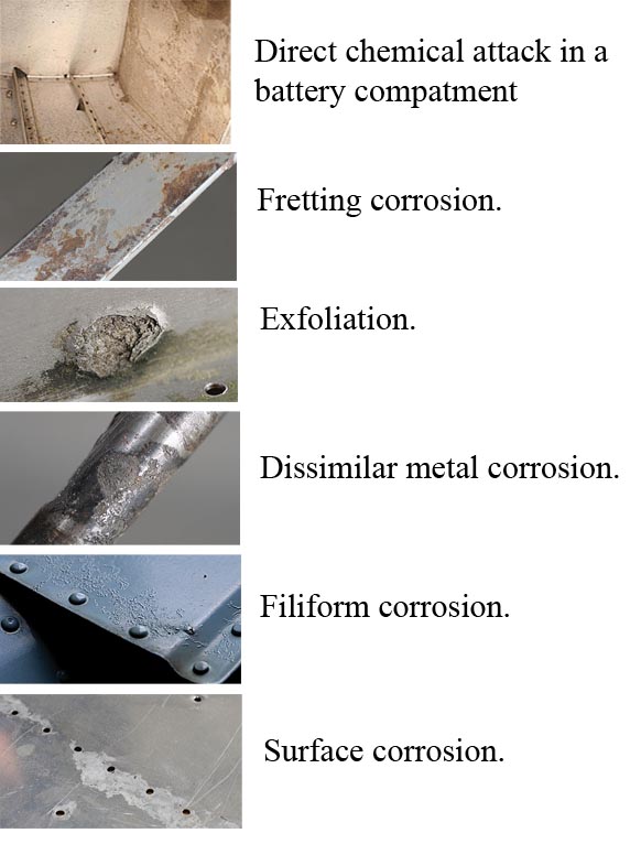
Direct chemical attack
Electrochemical attack
Direct Chemical Attack
Direct chemical attack, or pure chemical corrosion,
is an attack resulting from a direct exposure of a bare
surface to caustic liquid or gaseous agents.
The most common
agents causing direct chemical attack on aircraft
are:
(1) spilled battery acid or fumes from batteries;
(2) residual flux deposits resulting from inadequately
cleaned, welded, brazed, or soldered joints; and
(3) entrapped caustic cleaning solutions.
Electrochemical Attack
An electrochemical attack may be likened chemically
to the electrolytic reaction that takes place in electroplating,
anodizing, or in a dry cell battery. The reaction
in this corrosive attack requires a medium, usually
water, which is capable of conducting a tiny current
of electricity. When a metal comes in contact with a
corrosive agent and is also connected by a liquid or
gaseous path through which electrons may flow, corrosion
begins as the metal decays by oxidation.
Forms of Corrosion
Surface Corrosion -
Surface corrosion appears as a general roughening,
etching, or pitting of the surface of a metal, frequently
accompanied by a powdery deposit of corrosion products.
Closer inspection will
reveal the paint or plating is lifted off the surface in
small blisters which result from the pressure
Dissimilar Metal Corrosion -
Extensive pitting damage may result from contact
between dissimilar metal parts in the presence of a
conductor. While surface corrosion may or may not
be taking place, a galvanic action, not unlike electroplating,
occurs at the points or areas of contact where
the insulation between the surfaces has broken down
or been omitted. This electrochemical attack can be
very serious because in many instances the action is
taking place out of sight, and the only way to detect
it prior to structural failure is by disassembly and
inspection
Intergranular Corrosion
This type of corrosion is an attack along the grain
boundaries of an alloy and commonly results from a
lack of uniformity in the alloy structure.
Intergranular
corrosion may exist without visible surface evidence.
Very severe intergranular corrosion may sometimes
cause the surface of a metal to “exfoliate.”
Stress Corrosion
Stress corrosion occurs as the result of the combined
effect of sustained tensile stresses and a corrosive
environment. Stress corrosion cracking is found in
most metal systems; however, it is particularly characteristic
of aluminum, copper, certain stainless steels,
and high strength alloy steels (over 240,000 psi).
Fretting Corrosion
Fretting corrosion is a particularly damaging form
of corrosive attack that occurs when two mating surfaces,
normally at rest with respect to one another, are
subject to slight relative motion. It is characterized by
pitting of the surfaces and the generation of considerable
quantities of finely divided debris
Sunday, August 1, 2010


Subscribe to:
Posts (Atom)