A lightning detector is a device that detects lightning produced by thunderstorms. There are three primary types of detectors: ground-based systems using multiple antennas, mobile systems using a direction and a sense antenna in the same location (often aboard an aircraft), and space-based systems.
For more http://avionics0.blogspot.com/2010/12/lightning-detection.html
Monday, December 27, 2010
Sunday, December 26, 2010

Saturday, November 13, 2010
Flaps
Flaps are hinged surfaces on the trailing edge of the wings of a fixed-wing aircraft. As flaps are extended, the stalling speed of the aircraft is reduced, which means that the aircraft can fly safely at slower speeds (especially during take off and landing). Flaps are also used on the leading edge of the wings of some high-speed jet aircraft, where they may be called Krueger flaps.
Extending flaps increases the camber of the wing airfoil, thus raising the maximum lift coefficient. This increase in maximum lift coefficient allows the aircraft to generate a given amount of lift with a slower speed. Therefore, extending the flaps reduces the stalling speed of the aircraft
Extending flaps also increases drag. This can be beneficial in the approach and landing phase because it helps to slow the aircraft. Another useful side effect of flap deployment is a decrease in aircraft pitch angle. This provides the pilot with a greater view over the nose of the aircraft and allows a better view of the runway during approach and landing.
Some trailing edge flap systems increase the planform area of the wing in addition to changing the camber. In turn, the larger lifting surface allows the aircraft to generate a given amount of lift with a slower speed, thus further reducing stalling speed. Although this effect is very similar to increasing the lift coefficient, raising the planform area of the wing does not itself raise the lift coefficient. The Fowler flap is an example of a flap system that increases the planform area of the wing in addition to increasing the camber.

Triple-slotted trailing-edge flaps and leading edge Krueger (unslotted and slotted) flaps fully extended on a Boeing 747 for landing.
Types of flap systems include:
- Krueger flap: hinged flap on the leading edge. Often called a "droop".
- Plain flap: rotates on a simple hinge.
- Split flap: upper and lower surfaces are separate, the lower surface operates like a plain flap, but the upper surface stays immobile or moves only slightly.
- Gouge flap: a cylindrical or conical aerofoil section which rotates backwards and downwards about an imaginary axis below the wing, increasing wing area and chord without affecting trim. Invented by Arthur Gouge for Short Brothers in 1936.
- Fowler flap: slides backwards before hinging downwards, thereby increasing both camber and chord, creating a larger wing surface better tuned for lower speeds. It also provides some slot effect. The Fowler flap was invented by Harlan D. Fowler.
- Fairey-Youngman flap: moves body down before moving aft and rotating.
- Slotted flap: a slot (or gap) between the flap and the wing enables high pressure air from below the wing to re-energize the boundary layer over the flap. This helps the airflow to stay attached to the flap, delaying the stall.
- Blown flaps: systems that blow engine air over the upper surface of the flap at certain angles to improve lift characteristics.
Friday, November 12, 2010
Primary Flight Display (PFD)
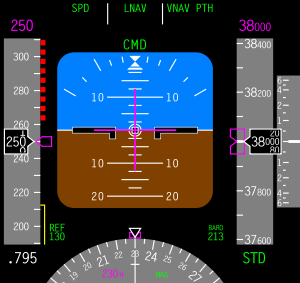
For more http://avionics0.blogspot.com/2010/11/primary-flight-display-pfd.html
Thursday, October 21, 2010
Thermal Anti-Icing System
Thermal systems used for the purpose of preventing the formation of ice or for deicing airfoil leading edges, usually use heated air ducted spanwise along the inside of the leading edge of the airfoil and distributed around its inner surface. However, electrically heated elements are also used for anti-icing and deicing airfoil leading edges.
There are several methods used to provide heated air. These include bleeding hot air from the turbine
compressor, engine exhaust heat exchangers, and ram air heated by a combustion heater.
There are several methods used to provide heated air. These include bleeding hot air from the turbine
compressor, engine exhaust heat exchangers, and ram air heated by a combustion heater.
Anti-Icing Using Cotibustion Heaters
Anti-icing systems using combustion heaters usually have a separate system for each wing and the empennage. A typical system of this type has the required number of combustion heaters located in each wing and in the empennage. A system of ducting and valves controls the airflow. The anti-icing system is automatically controlled by overheat switches, thermal cycling switches, a balance control, and a duct pressure safety switch The overheat and cycling switches allow the heaters to operate at periodic intervals, and they also stop
heater operation completely if overheating occurs.
Anti-Icing Using Exhaust Heaters
Anti-icing of the wing and tail leading edges is accomplished by a controlled flow of heated air from heat muffs around a reciprocating engine’s tail pipe. In some installations this assembly is called an augmentor.
Anti-icing of the wing and tail leading edges is accomplished by a controlled flow of heated air from heat muffs around a reciprocating engine’s tail pipe. In some installations this assembly is called an augmentor.
Normally, heated air from either engine supplies the wing leading edge anti-icing system in the same wing section. During single engine operation, a crossover duct system interconnects the left and right wing leading edge ducts. This duct supplies heated air to the wing section normally supplied by the inoperative engine. Check valves in the crossover duct prevent the reverse flow of heated air and also prevent cold air from entering the anti-icing system from the inoperative engine.
Anti Icing using Engine Bleed Air
Heated air for anti.icing is obtained by bleeding air from the engine compressor. The reason for the use of such a system is that relatively large amounts of very hot air can be tapped off the compressor, providing a satisfactory source of anti-icing and deicing heat.
The shut off valve for each anti-icing section is a pressure regulating type. The valve controls the flow of air from the bleed air system to the ejectors, where it is ejected through small nozzles into mixing chambers. The hot bleed air is mixed with ambient air.
Monday, October 11, 2010
Cabin Pressurization
Cabin pressurization is the active pumping of compressed air into an aircraft cabin when flying at altitude to maintain a safe and comfortable environment for crew and passengers in the low outside atmospheric pressure.
Pressurization is essential over 3,000 metres (9,800 ft) above sea level to protect crew and passengers from the risk of hypoxia and a number of other physiological problems in the thin air above that altitude and increases passenger comfort generally. "The outflow valve is constantly being positioned to maintain cabin pressure as close to sea level as practical, without exceeding a cabin-to-outside pressure differential of 8.60 psi."
Maintaining the cabin pressure altitude to below 3,000 metres (9,800 ft) generally avoids significant hypoxia, altitude sickness, decompression sickness and barotrauma. Emergency oxygen systems are installed, both for passengers and cockpit crew, to prevent loss of consciousness in the event that cabin pressure rapidly rises above 10,000 feet MSL. Those systems contain more than enough oxygen for all on board, to give the pilot adequate time to descend the plane to a safe altitude, where supplemental oxygen is not needed. Federal Aviation Administration (FAA) regulations in the U.S. mandate that the cabin altitude may not exceed 8,000 feet at the maximum operating altitude of the airplane under normal operating conditions.
The pressure maintained within the cabin is referred to as the equivalent effective cabin altitude or more normally, the "cabin altitude". Cabin altitude is not normally maintained at average mean sea level (MSL) pressure (1013.25 hPa, or 29.921 inches of mercury) throughout the flight, because doing so would cause the designed differential pressure limits of the fuselage to be exceeded. An aircraft planning to cruise at 40,000 ft (12,000 m) is programmed to rise gradually from take-off to around 8,000 ft (2,400 m) in cabin pressure altitude, and to then reduce gently to match the ambient air pressure of the destination.
Pressurization is achieved by the design of an airtight fuselage engineered to be pressurized with a source of compressed air and controlled by an environmental control system (ECS). The most common source of compressed air for pressurization is bleed air extracted from the compressor stage of a gas turbine engine, from a "low" or "intermediate" stage and also from an additional "high" stage. "The exact stage can vary, depending on engine type." By the time the cold outside air has reached the bleed air valves, it has been heated to around 200 °C (392 °F) and is at a very high pressure. The control and selection of high or low bleed sources is fully automatic and is governed by the needs of various pneumatic systems at various stages of flight.
The part of the bleed air that is directed to the ECS, is then expanded and cooled to a suitable temperature by passing it through a heat exchanger and air cycle machine ('the packs system'). In some of the larger airliners, hot trim air can be added downstream of air conditioned air coming from the packs, if it is needed to warm a section of the cabin that is colder than other sections
All exhaust air is dumped to atmosphere via an outflow valve, usually at the rear of the fuselage. This valve controls the cabin pressure and also acts as a safety relief valve, in addition to other safety relief valves. In the event that the automatic pressure controllers fail, the pilot can manually control the cabin pressure valve, according to the backup emergency procedure checklist. The automatic controller normally maintains the proper cabin pressure altitude by constantly adjusting the outflow valve position, so that the cabin pressure is as near to sea level pressure as practical, without exceeding the maximum differential limit of 8.60 psi. At 39,000 feet, the cabin pressure would be automatically maintained at about 6,900 feet (450 feet lower than Mexico City), which is about 11.5 psi of atmosphere pressure (76 kPa)
Saturday, September 25, 2010
Environmental Control System (ECS)
The Environmental Control System of an airliner provides air supply, thermal control and cabin pressurization for the passengers and crew. Avionics cooling, smoke detection, and fire suppressionare also commonly considered part of the Environmental Control System.

On most jetliners, air is supplied to the ECS by being "bled" from a compressor stage of each gas turbine engine, upstream of the combustor. The temperature and pressure of this "bleed air" varies widely depending upon which compressor stage and the RPM of the engine.
A "Manifold Pressure Regulating Shut-Off Valve" (MPRSOV) restricts the flow as necessary to maintain the desired pressure for downstream systems. This flow restriction results in efficiency losses. To reduce the amount of restriction required, and thereby increase efficiency, air is commonly drawn from two bleed ports (3 on the Boeing 777).
When the engine is at low thrust, the air is drawn from the "High Pressure Bleed Port." As thrust is increased, the pressure from this port rises until "crossover," where the "High Pressure Shut-Off Valve" (HPSOV) closes and air is thereafter drawn from the "Low Pressure Bleed Port."
To achieve the desired temperature, the bleed-air is passed through a heat exchanger called a "pre-cooler." Air from the jet engine fan is blown across the pre-cooler, which is located in the engine strut. A "Fan Air Modulating Valve" (FAMV) varies the cooling airflow, and thereby controls the final air temperature of the bleed air.
The Cold Air Unit, or "Airconditioning pack" is usually an air cycle machine (ACM) cooling device. Some aircraft, including early 707 jetliners, used vapor-compression refrigeration like that used in home air conditioners.
On most jetliners, the A/C packs are located in the "Wing to Body Fairing" between the two wings beneath the fuselage. On some jetliners (Douglas Aircraft DC-9 Series) the A/C Packs are located in the tail. The A/C Packs on the McDonnell Douglas DC-10/MD-11 and LockheedL-1011 are located in the front of the aircraft beneath the flight deck. Nearly all jetliners have two packs, although larger aircraft such as the Boeing 747, Lockheed L-1011, and McDonnell-Douglas DC-10/MD-11 have three.
The quantity of bleed air flowing to the A/C Pack is regulated by the "Flow Control Valve" (FCV). One FCV is installed for each pack. A normally closed "isolation valve" prevents air from the left bleed system from reaching the right pack (and v.v.), although this valve may be opened in the event of loss of one bleed system.
The A/C Pack exhaust air is ducted into the pressurized fuselage, where it is mixed with filtered air from the recirculation fans, and fed into the "mix manifold". On nearly all modern jetliners, the airflow is approximately 50% "outside air" and 50% "filtered air."
Modern jetliners use "High Efficiency Particulate Arresting" HEPA filters, which trap >99% of all bacteria and clustered viruses.
Airflow into the fuselage is approximately constant, and pressure is maintained by varying the opening of the "Out Flow Valve" (OFV). Most modern jetliners have a single OFV located near the bottom aft end of the fuselage, although some larger aircraft like the 747 and 777 have two.
In the event the OFV should fail closed, at least two Positive Pressure Relief Valves (PPRV) and at least one Negative Pressure Relief Valve (NPRV) are provided to protect the fuselage from over- and under- pressurization.
The atmosphere at typical jetliner cruising altitudes is generally very dry and cold, and the outside air pumped into the cabin on a long flight typically has a relative humidity around 10%. The fact that cabin pressure is generally lower than the pressure at ground level does not of itself contribute to the dryness.
Thursday, September 16, 2010
AIRCRAFT MASS AND BALANCE
AIRCRAFT MASS AND BALANCE
The main purposes, of monitoring the mass and balance of aircraft, are to maintain safety and to achieve efficiency in flight. The position of loads such as passengers, fuel, cargo and equipment will alter the position of the Centre of Gravity (CG) of the aircraft.
Incorrect loading will affect the aircraft rate of climb, manoeuvrability, ceiling, speed and fuel consumption. If the CG were too far forward, it would result in a nose-heavy condition, which could be potentially dangerous on take-off and landing. If the CG is too far aft, the tail-heavy condition will increase the tendency of the aircraft to stall and make landing more difficult.
Stability of the aircraft will also be affected with the CG outside the normal operational limits. Provided the CG lies within specified limits, the aircraft should be safe to fly. The unit of measurement for mass and balance are normally dictated by the aircraft manufacturer and can be either Metric or Imperial terms. Specific definitions for mass and balance ensure they are correctly interpreted.
• Datum: The datum is an imaginary vertical plane from which horizontal measurements are taken. The locations of items such as baggage compartments, fuel tanks, seats and engines are relevant to the datum. There is no fixed rule for the location of the datum. The manufacturer will normally specify the nose of the aircraft, but it could be at the front main bulkhead or even forward of the aircraft nose
• Arm: The horizontal distance from an item or piece of equipment to the datum. The arm's distance is usually measured in inches (or millimetres) and may be preceded by a plus (+) or a minus (-) sign. The plus sign indicates that the distance is aft of the datum and the minus sign indicates distance is forward of the datum
• Moment: The product of a force multiplied by the distance about which the force acts. In the case of mass and balance, the force is the mass (kg/lb) and the distance is the arm (m/in). Therefore, a mass of 40 kilograms, at 3 metres aft of the datum will have a moment of 40 x 3 = 120 kg/m. It is important to consider whether a value is positive (+ve) or negative (-ve) when moments are calculated and the following conventions are used:
Distances horizontal: aft of the datum (+), forward of the datum (-).
Weight: added (+), removed (-).
• Centre of Gravity (CG): This is the point about which all of the mass of the aircraft or object is concentrated. An aircraft could be suspended from this point and it would not adopt a nose-down nor a tail-down attitude.
• Centre of Gravity Balance Limits: For normal operation of the aircraft, the CG should be between the Forward and Aft limits as specified by the manufacturer. If the CG is outside these limits, the aircraft performance will be affected and the aircraft may be unsafe.
• Dry Operating Mass: The total mass of the aeroplane, ready for a specific type of operation, excluding all usable fuel and traffic load. This mass includes crew and crew baggage, catering and removable passenger service equipment, potable water and lavatory chemicals.
• Maximum Zero Fuel Mass: The maximum permissible mass of an aircraft with no usable fuel. Fuel contained in certain tanks must be included if this is explicitly mentioned in the aircraft’s Flight Manual limitations.
• Maximum Structural Take-Off Mass (MTOM): The maximum permissible total aeroplane mass at the start of the take-off run.
• Maximum Structural Landing Mass: The maximum permissible total aeroplane mass upon landing under normal circumstances.
• Traffic Load: This includes the total mass of passengers, baggage and cargo, including any non-revenue load.
Mass and Balance Documentation
The Mass and Balance documentation used by an operator must include certain basic information, which is listed below. Subject to the approval of the authority, some of this information may be omitted.
A. Aeroplane registration and type
B. Flight identification number and date
C. Identity of the commander
D. Identity of the person who prepared the document
E. Dry operating mass and the corresponding CG of the aeroplane
F. Mass of the fuel at take-off and the mass of trip fuel
G. Mass of consumables other than fuel
H. Load components that include passengers, baggage, freight and ballast
I. Take-off Mass, Landing Mass and Zero Fuel mass.
J. The load distribution
K. Aeroplane CG positions
L. Limiting mass and CG values
FREQUENCY OF WEIGHING
Aircraft must be weighed before entering service, to determine the individual mass and CG position. This should be done once all manufacturing processes have been completed. The aircraft must also be re-weighed within four years from the date of manufacture, if individual mass is used, or within nine years from the date of manufacture, if fleet masses are used.
The mass and CG position of an aircraft must be periodically re-established. The maximum interval between one aircraft weigh and the next, must be defined by the operator, but not exceed the four/nine year limits
15.7 CALCULATION OF MASS AND CG OF ANY SYSTEM
The position of the CG of any system (refer to Fig. 1) may be found using the following process:
• Total Mass is calculated, by adding the mass of each load (plus the mass of the beam)
• The moment of each load is calculated, by multiplying the mass by the arm (distance from the reference datum)
• ALL the moments are added together, to provide the Total Moment
• Total Moment is divided by the Total Mass to give CG position.
Saturday, September 4, 2010
Aviation Hydraulic Oil
Aircraft hydraulic fluids fall under various specifications:
Common petroleum-based:
- Mil-H-5606: Mineral base, flammable, fairly low flashpoint, usable from −65 °F (−54 °C) to 275 °F (135 °C), red color
- Mil-H-83282: Synthetic hydrocarbon base, higher flashpoint, self-extinguishing, backward compatible to -5606, red color, rated to −40 °F (−40 °C) degrees.
- Mil-H-87257: A development of -83282 fluid to improve its low temperature viscosity.
Phosphate-ester based:
- BMS 3-11: Skydrol 500B-4, Skydrol LD-4, Skydrol 5 and Exxon HyJetIV-A plus – Typically light purple, not compatible with petroleum-based fluids, will not support combustion.
Radial Engines
Radial Engines


Nose Section
In general, it is either tapered or round in order to
place the metal under tension or compression instead
of shear stresses.
A tapered nose section is
used quite frequently on direct-drive, low-powered
engines, because extra space is not required to house
the propeller reduction gear.
The nose section on engines which develop from
1,000 to 2,500 hp. is usually rounded and sometimes
ribbed to get as much strength as possible.
Aluminum alloy is the most widely used material
because of its adaptability to forging processes and
its vibration-absorbing characteristics.
Since the nose section transmits many varied
forces to the main or power section, it must be
properly secured to transmit the loads efficiently.
It also must have intimate contact to give rapid and
uniform heat conduction, and be oiltight to prevent
leakage. This is usually accomplished by an offset
or ground joint, secured by studs or capscrews.
On some of the larger engines, a small chamber
is located on the bottom of the nose section to collect
the oil. This is called the nose section oil sump.
Power Section
On engines equipped with a two-piece master rod
and a solid-type crankshaft, the main or power
crankcase section may be solid, usually of aluminum
alloy.
This portion of the engine is often called the
power section, because it is here that the reciprocating
motion of the piston is converted to rotary
motion of the crankshaft.
Because of the tremendous loads and forces from
the crankshaft assembly and the tendency of the
cylinders to pull the crankcase apart, especially in
extreme conditions when a high-powered engine is
detonated, the main crankcase section must be very
well designed and constructed.
The machined surfaces on which the cylinders
are mounted are called cylinder pads. They are
provided with a suitable means of retaining or
fastening the cylinders to the crankcase.
The inner portion of the cylinder pads are sometimes
chamfered or tapered to permit the installation
of a large rubber O-ring around the cylinder
skirt, which effectively seals the joint between the
cylinder and the crankcase pads against oil leakage.
Diffuser Section
The diffuser or supercharger section generally is
cast of aluminum alloy, although, in a few cases,
the lighter magnesium alloy is used.
Because of the elongation and contraction of the
cylinders, the intake pipes which carry the mixture
from the diffuser chamber through the intake valve
ports are arranged to provide a slip joint which
must be leakproof. The atmospheric pressure on
the outside of the case of an unsupercharged engine
will be higher than on the inside, especially when
the engine is operating at idling speed. If the
engine is equipped with a supercharger and operated
at full throttle, the pressure will be considerably
higher on the inside than on the outside of the case.
If the slip joint connection has a slight leakage,
the engine may idle fast due to a slight leaning of
the mixture. If the leak is quite large, it may not
idle at all. At open throttle, a small leak probably
would not be noticeable in operation of the engine,
but the slight leaning of the fuel/air mixture might
cause detonation or damage to the valves and valve
seats.
Accessory Section
The accessory (rear) section usually is of cast
construction, and the material may be either aluminum
alloy, which is used most widely, or magnesium,
which has been used to some extent.
the
increased demands for electric current on large
aircraft and the requirements of higher starting
torque on powerful engines have resulted in an
increase in the size of starters and generators.
This means that a greater number of mounting bolts
must be provided and, in some cases, the entire
rear section strengthened.
In some cases there is a duplication of drives,
such as the tachometer drive, to connect instruments
located at separate stations.
The accessory section provides a mounting place
for the carburetor, or master control, fuel injection
pumps, engine-driven fuel pump, tachometer
generator, synchronizing generator for the engine
analyzer, oil filter, and oil pressure relief valve.
Friday, August 27, 2010
Bleeding a Shock Strut
Bleeding a Shock Strut
If the fluid level of a shock strut has becomeextremely low, or if for any other reason air is
trapped in the strut cylinder, it may be necessary to bleed the strut during the servicing operation. Bleeding is usually performed with the aircraft placed on jacks. In this position the shock struts can be extended and compressed during the filling operation, thus expelling all the entrapped air. The following is a typical bleeding procedure :
Construct a bleed hose containing a fitting suitable for making an airtight connection to the shock strut filler opening. The base should be long enough to reach from the when the aircraft is on jacks.
Jack the aircraft until all shock struts are fully extended.
Release the air pressure in the strut to bebled.
Remove the air valve assembly.
Fill the strut to the level of the filler port with an approved type hydraulic fluid.
Attach the bleed hose to the filler port and insert the free end of the hose into a container of clean hydraulic fluid, making sure that this end of the hose is below the surface of the hydraulic fluid.
Place an exerciser jack or other suitable single-base jack under the shock strut jacking point. Compress and
extend the strut fully by raising and lowering the jack until the flow of air bubbles from the strut has completely stopped.
Compress the strut slowly and allow it to extend by its own weight.
Remove the exerciser jack, and then lower and remove all other jacks.
Remove the bleed hose from the shock strut.
Install the air valve and inflate the strut
Landing Gear System

Undercarriage Configuration
1. Conventiol -Main wheel + tail wheel
2. Tricycle - Main wheel + nose wheel
3. Tandom. - Main wheel + out trigger wheels
Shock Struts
Shock struts are self-contained hydraulic units that support an aircraft on the ground and protect
the aircraft structure by absorbing and dissipating the tremendous shock loads of landing. Shock struts must be inspected and serviced regularly to function efficiently.
SHIMMY DAMPERS
A shimmy damper controls vibration, or shimmy, through hydraulic damping. The damper is either attached to or built integrally with the nose gear and prevents shimmy of the nosewheel during taxiing, landing, or takeoff. There are three types of shimmy dampers commonly used on aircraft:
(1)The piston type,
(2) vane type, and
(3) features incorporated in the nosewheel power steering system of some aircraft.
Steer Damper
A steer damper is hydraulically operaied and accomplishes the two separate functions of steering
and/or eliminating shimmying.
Thursday, August 19, 2010

Sunday, August 15, 2010
ICAO phonetic alphabet
ICAO phonetic alphabet :
A ALPHA AL fah
B BRAVO BRAH VO
C CHARLIE CHAR lee
D DELTA DELL tah
E ECHO ECK oh
F FOXTROT FOKS trot
G GOLF GOLF
H HOTEL hoh TELL
I INDIA IN dee ah
J JULIETT JEW lee ETT
K KILO KEY loh
L LIMA LEE mah
M MIKE MIKE
N NOVEMBER no VEM ber
O OSCAR OSS cah
P PAPA pah PAH
Q QUEBEC keh BECK
R ROMEO ROW me oh
S SIERRA see AIR ah
T TANGO TANG go
U UNIFORM YOU nee form
V VICTOR VIK tah
W WHISKEY WISS key
X X-RAY ECKS RAY
Y YANKEE YANG key
Z ZULU ZOO loo
Friday, August 13, 2010
GPWS (Ground Proximity Warning System)
GPWS (Ground Proximity Warning System)
A ground proximity warning system (GPWS) is a system designed to alert pilots if their aircraft is in immediate danger of flying into the ground or an obstacle.
More advanced systems, introduced in 1996, are known as enhanced ground proximity warning systems (EGPWS) .sometimes confusingly called terrain awareness warning systems.
For more information..
http://avionics0.blogspot.com/2010/08/gpws-ground-proximity-warning-system.html
Tuesday, August 10, 2010
Aircraft Avionics Systems
Full Categorized aircraft avionics equipment list,
http://avionics0.blogspot.com/p/avionics-in-aircraft.html
http://avionics0.blogspot.com/p/avionics-in-aircraft.html
Sunday, August 8, 2010
CFM and GE certify third engine in two weeks

For the third time in two weeks, CFM (GE & Snecma) and GE have announced certification of new engine variants. Most recently on July 30, CFM was granted certification of the updated CFM56-7BE engine, which will enter service in mid-2011 on the Boeing 737.
The -7BE evolution engine will fly in the fourth quarter on a Continental 737-800, as Boeing looks to deliver at least 2% improvement in fuel burn to its existing single-aisle product line. The company test flew the new nacelle design in August 2009.
The engine features a revised high pressure turbine guide vane diffuser, improved high pressure turbine blades, disc and a revised forward outer seal, along with improvements low pressure turbine blades, vanes, discs and case.
While CFM outwardly states that the engine will contribute 1% improvement on its own, testing has found that the engine will deliver 1.6% improvement in fuel burn. An additional 1% will come from aerodynamic refinements to the exterior of the 737.
The CFM56-7BE engine is part of a host of improvements to the 737, which also include the Boeing Sky Interior, which will enter service with flyDubai, the first of 37 customers later this year.
Wednesday, August 4, 2010
Aircraft Hydraulic Fluids
Aircraft hydraulic fluids fall under various specifications:
Common petroleum-based:
Common petroleum-based:
- Mil-H-5606: Mineral base, flammable, fairly low flashpoint, usable from −65 °F (−54 °C) to 275 °F (135 °C), red color
- Mil-H-83282: Synthetic hydrocarbon base, higher flashpoint, self-extinguishing, backward compatible to -5606, red color, rated to −40 °F (−40 °C) degrees.
- Mil-H-87257: A development of -83282 fluid to improve its low temperature viscosity.
Aircraft Ground Checks
Ground Checks
Before the pilot starts to carry out checks on the aircraft itself, it is important to check
the area around the aircraft. The pilot will be looking out for a number of things.
The position of the aircraft in relation to other things to ensure there is room to
manoeuvre the aircraft safely..
The area is free of rubbish and stones which could be picked-up by jet intakes or
propellers.
The aircraft has chocks in place (until parking brakes are on).
Fire extinguishers are readily available.
External Aircraft Checks
Many faults or potential problems can be discovered by carrying out visual checks on
the aircraft. Before flying the pilot will walk around the aircraft systematically to
ensure nothing is missed out. In addition to making an inspection of specific parts of
the aircraft, the pilot must look out for damage or wear on the 'skin', 'popped' rivets,
and leaking oil, fuel or hydraulic fluid. A typical walk round could be as follows.
1. Cockpit
Check Magneto Switches are Off (the Magneto Switches are part of the ignition
system in the aircraft).
Makes sure brakes are set to PARK
Flaps should be lowered ready for inspection
Check door locks.
Switch on navigation lights
2. Port Left Undercarriage
Hydraulic fluid leaks.
Condition of tyres and tyre pressure.
Condition of pads and callipers
Look around for any signs of fluid leakage from any other part of the aircraft.
3. Port Fuselage
Check surfaces for ice or damage
Make sure any windows are clean and in good condition
4. Port Tail Plane
Check surfaces for ice or damage
5. Port Elevator
Make sure it has full and free movement
Check for damage and make sure it is secure
Check control linkage mechanism
6. Tail Fin
Check both sides for ice or damage
Make sure it is secure
Check navigation light
7. Rudder
Check both sides for ice and damage
Make sure it has full and free movement
Check control linkage mechanism
The pilot will then work along the starboard (right) of the aircraft repeating the checks
above in the following order.
8. Starboard Elevator.
9. Starboard Tail Plane
10. Starboard Fuselage
11. Starboard Undercarriage
Once these checks have been completed the pilot will now need to look at the aircraft
wing.
12. Starboard Flap
Check for ice and damage.
Make sure drain holes are clear.
Ensure flap is secure.
13. Starboard Aileron
Check for ice and damage.
Check for full and free movement.
Ensure drain holes are clear.
14. Wing Tip
Check for ice and damage
Check navigation light.
15. Leading Edge
Check for ice and damage.
16. Upper Wing Surface
Check for ice and damage
17. Lower Wing Surface
Check for ice and damage
18. Engine
Open the engine inspection panel and check oil level and inspect engine for
loose wires. Make sure intake and air filter is clean and not blocked.
19. Propeller
If the aircraft has a propeller check it for damage and make sure it is secure.
The pilot now needs to carry out the wing checks on the left in the following order.
20. Lower Wing Surface
21. Upper Wing Surface
22. Leading Edge
23. Wing Tip
24. Port Aileron
25. Port Flap
In addition to these checks the pilot will need to ensure that all tie downs are
removed, check the fuel level, and all covers protecting parts of the aircraft such as
exhaust and pitot head and vents are removed.
Look at the diagram below. The numbers correspond to the checks above.
Monday, August 2, 2010
CORROSION (AME M-7)
CORROSION
Many aircraft structures are made of metal, and the
most insidious form of damage to those structures is
 corrosion. From the moment the metal is manufactured,
it must be protected from the deleterious effects
of the environment that surrounds it.
Water or water vapor containing salt combines with
oxygen in the atmosphere to produce the main source
of corrosion in aircraft. Aircraft operating in a marine
environment, or in areas where the atmosphere contains
industrial fumes that are corrosive, are particularly
susceptible to corrosive attacks
The appearance of corrosion varies with
the metal. On the surface of aluminum alloys and
magnesium, it appears as pitting and etching,
often combined with a gray or white powdery deposit.
On copper and copper alloys, the corrosion forms a
greenish film; on steel, a reddish corrosion byproduct
commonly referred to as rust.
Types of Corrosion
Direct chemical attack
Electrochemical attack
Direct Chemical Attack
Direct chemical attack, or pure chemical corrosion,
is an attack resulting from a direct exposure of a bare
surface to caustic liquid or gaseous agents.
The most common
agents causing direct chemical attack on aircraft
are:
(1) spilled battery acid or fumes from batteries;
(2) residual flux deposits resulting from inadequately
cleaned, welded, brazed, or soldered joints; and
(3) entrapped caustic cleaning solutions.
Electrochemical Attack
An electrochemical attack may be likened chemically
to the electrolytic reaction that takes place in electroplating,
anodizing, or in a dry cell battery. The reaction
in this corrosive attack requires a medium, usually
water, which is capable of conducting a tiny current
of electricity. When a metal comes in contact with a
corrosive agent and is also connected by a liquid or
gaseous path through which electrons may flow, corrosion
begins as the metal decays by oxidation.
Forms of Corrosion
Surface Corrosion -
Surface corrosion appears as a general roughening,
etching, or pitting of the surface of a metal, frequently
accompanied by a powdery deposit of corrosion products.
Closer inspection will
reveal the paint or plating is lifted off the surface in
small blisters which result from the pressure
Dissimilar Metal Corrosion -
Extensive pitting damage may result from contact
between dissimilar metal parts in the presence of a
conductor. While surface corrosion may or may not
be taking place, a galvanic action, not unlike electroplating,
occurs at the points or areas of contact where
the insulation between the surfaces has broken down
or been omitted. This electrochemical attack can be
very serious because in many instances the action is
taking place out of sight, and the only way to detect
it prior to structural failure is by disassembly and
inspection
Intergranular Corrosion
This type of corrosion is an attack along the grain
boundaries of an alloy and commonly results from a
lack of uniformity in the alloy structure.
Intergranular
corrosion may exist without visible surface evidence.
Very severe intergranular corrosion may sometimes
cause the surface of a metal to “exfoliate.”
Stress Corrosion
Stress corrosion occurs as the result of the combined
effect of sustained tensile stresses and a corrosive
environment. Stress corrosion cracking is found in
most metal systems; however, it is particularly characteristic
of aluminum, copper, certain stainless steels,
and high strength alloy steels (over 240,000 psi).
Fretting Corrosion
Fretting corrosion is a particularly damaging form
of corrosive attack that occurs when two mating surfaces,
normally at rest with respect to one another, are
subject to slight relative motion. It is characterized by
pitting of the surfaces and the generation of considerable
quantities of finely divided debris
Sunday, August 1, 2010


Saturday, July 31, 2010
Non Return Valve
NON RETURN VALVE
A check valve, clack valve, non-return valve or one-way valve is a mechanical device, a valve, which normally allows fluid to flow through it in only one direction.
Check valves are two-port valves, meaning they have two openings in the body, one for fluid to enter and the other for fluid to leave.
is a check valve in which the closing member, the movable part to block the flow, is a spherical ball. In some (but not all) ball check valves, the ball is spring-loaded to help keep it shut. For those designs without a spring, reverse flow is required to move the ball toward the seat and create a seal
Diaphragm check valve -
uses a flexing rubber diaphragm positioned to create a normally-closed valve. Pressure on the upstream side must be greater than the pressure on the downstream side by a certain amount, known as the pressure differential, for the check valve to open allowing flow. Once positive pressure stops, the diaphragm automatically flexes back to its original closed position.
Swing check valve or Tilting disc check valve -
is check valve in which the disc, the movable part to block the flow, swings on a hinge or trunnion, either onto the seat to block reverse flow or off the seat to allow forward flow. The seat opening cross-section may be perpendicular to the centerline between the two ports or at an angle
Stop-check valve -
is a check valve with override control to stop flow regardless of flow direction or pressure. In addition to closing in response to backflow or insufficient forward pressure (normal check-valve behavior), it can also be deliberately shut by an external mechanism, thereby preventing any flow regardless of forward pressure.
Lift-check valve -
is a check valve in which the disc, sometimes called a lift, can be lifted up off its seat by higher pressure of inlet or upstream fluid to allow flow to the outlet or downstream side. A guide keeps motion of the disc on a vertical line, so the valve can later reseat properly. When the pressure is no longer higher, gravity or higher downstream pressure will cause the disc to lower onto its seat, shutting the valve to stop reverse flow.
Duckbill valve -
is a check valve in which flow proceeds through a soft tube that protrudes into the downstream side. Back-pressure collapses this tube, cutting off flow.
A check valve, clack valve, non-return valve or one-way valve is a mechanical device, a valve, which normally allows fluid to flow through it in only one direction.
Check valves are two-port valves, meaning they have two openings in the body, one for fluid to enter and the other for fluid to leave.
Types of check valves
Ball check valve -is a check valve in which the closing member, the movable part to block the flow, is a spherical ball. In some (but not all) ball check valves, the ball is spring-loaded to help keep it shut. For those designs without a spring, reverse flow is required to move the ball toward the seat and create a seal
Diaphragm check valve -
uses a flexing rubber diaphragm positioned to create a normally-closed valve. Pressure on the upstream side must be greater than the pressure on the downstream side by a certain amount, known as the pressure differential, for the check valve to open allowing flow. Once positive pressure stops, the diaphragm automatically flexes back to its original closed position.
Swing check valve or Tilting disc check valve -
is check valve in which the disc, the movable part to block the flow, swings on a hinge or trunnion, either onto the seat to block reverse flow or off the seat to allow forward flow. The seat opening cross-section may be perpendicular to the centerline between the two ports or at an angle
Stop-check valve -
is a check valve with override control to stop flow regardless of flow direction or pressure. In addition to closing in response to backflow or insufficient forward pressure (normal check-valve behavior), it can also be deliberately shut by an external mechanism, thereby preventing any flow regardless of forward pressure.
Lift-check valve -
is a check valve in which the disc, sometimes called a lift, can be lifted up off its seat by higher pressure of inlet or upstream fluid to allow flow to the outlet or downstream side. A guide keeps motion of the disc on a vertical line, so the valve can later reseat properly. When the pressure is no longer higher, gravity or higher downstream pressure will cause the disc to lower onto its seat, shutting the valve to stop reverse flow.
Duckbill valve -
is a check valve in which flow proceeds through a soft tube that protrudes into the downstream side. Back-pressure collapses this tube, cutting off flow.

RECIPROCATING ENGINE OVERHAUL (M-16)
Tools and equipment
An engine overhaul does require some special tools. These tools are used for measuring clearances as well as special assembly or disassembly procedures unique to the engine.
Here's a list of tools that you might need. The list will vary for different types of engines, and this list is for the Continental O-470. For tools that are unique to the engine, you should consult the engine overhaul manual. Note that the overhaul manual will often list many special and highly expensive tools that the factory uses but that you don't need to complete an overhaul.
If you're working with a mechanic, chances are the mechanic already has these tools and through negotiation you can use your mechanic's tools. Make sure you respect your mechanic's tools.
As somebody who does a lot of maintenance,
Hand Tools
General hand tools: You'll need the following (all in fractional inch sizes - no metric). I recommend the high-quality full polish Craftsman or Snap-On tools.
• Short-pattern "stubby" box-end wrench set, 1/4" to 3/4"
• Long-pattern box-end wrench set, up to 1" size
• 60 degree double-offset box-end short-pattern wrench set (Snap-On makes an excellent set, and they're sometimes necessary for tight fits).
• X-Acto knife, angle blades and flat blades for gasket scraping.
• Cotter key puller tool
• Duckbill and needlenose pliers
• Small set of snips
• Crescent F-wrench with 2" capacity
• 1/4" drive 12 pt shallow socket set and drivers, with extension set
• 3/8" drive 12 pt shallow socket set and drivers, with extension set
• Assorted screwdrivers
• Allen key set
• Brass hammer
• Soft mallet
• Cleaning brushes
• Drifts of various sizes to help with assembly
You might also find yourself in need of deep sockets and/or universal drive sockets, depending on the engine.
You must have a good, calibrated, torque wrench for any overhaul. I prefer the "clicker" type of torque wrench where you pre-set a torque value and then turn until the wrench "clicks" off at that specified value. The clicker types are more expensive than the beam type wrenches where you read the torque off of a scale attached to the wrench. Both work equally well assuming the wrench has been calibrated.
You'll typically want a small and a large wrench for convenience. A small wrench is best for the smaller jobs and tight clearances, and it is lighter. A large wrench is handy for leverage when doing the larger torque values like through-studs. Your wrenches should have a range of about 50 inch-lbs up to about 800 inch-lbs.
Specialty Tools
There are a number of specialty tools that are required for any given aviation engine. Many of these tools have use in regular maintenance outside of overhauls, so they're handy to have around all the time.
Aviation spark plug socket. You need a special socket for aviation plugs. Make sure you have adapters for your torque wrench's drive size.
Cylinder base wrench set. These wrenches are strangely bent to allow you to get to the cylinder base nuts when the cylinders are installed on the engine. There are different sizes required for different engines so make sure you check sizes.
Piston Ring Compressor. I recommend the wrinkle-band type. Make sure you get one large enough for your engine. Many automotive compressors are not large enough for aircraft pistons.
Timing disk and propeller dome adapter, and magneto timing box. To set timing on the engine after reassembly.
Pushrod Tube Spring Compressor. Necessary when installing Continental engine pushrod housings.
Valve spring compressor. If you're doing top end work, you should get this specialty compressor tool.
Bearing puller. Might be necessary for disassembling accessory drives.
Engine crane. Get a portable hydraulic shop crane from your local auto parts store. Usually these come in a 2 ton capacity and can often by found with folding legs to make storage easier.
Engine stand. Check Trade-A-Plane for engine stand ads. Do not attempt an overhaul without a stand. You should also get the rolling casters so that you can move the engine around during the overhaul.
Safety wire twister pliers. I recommend getting a good set of twisters, not a cheapo import. Robinson and Milbar are the best. I particularly recommend the Milbar Tigerwave 6" and 9" twisters.
Measuring tools. You're generally going to need:
Outside Micrometers. A good mix is 0-1" and 1-2" fixed, and a 0-6" interchangable anvil set
Snap-gauges, buy a set up to about 6 inches.
Bore gauge, up to 6".
I prefer direct digital-reading equipment to minimize confusion, but that costs more than the old style analog gauges and both work equally well. Mitutoyu Digimatic or Starrett are good brands. McMaster-Carr is a good supplier.
Documentation
You will absolutely need a copy of the engine overhaul manual and the parts manual. The best source for these is the factory.
You should also have a copy of the latest service bulletins for the engine, also available from the factory.
While you are removing your engine and disassembling it, make sure you document the existing installation. I recommend a decent digital camera for convenience. Having the photos provides for a record both during reassembly and useful documentation of the engine's previous condition and its overhauled state that you should include with the engine records.
Supplies
Get a bunch of plastic ziplock bags and 3x5 index cards to bag and tag parts as you remove them. I buy the sandwich size and the 1 gallon freezer-bag size.
Aero grade Hylomar. Gasket and parting seam sealant. Great stuff.
Safety wire. You'll need 0.020, 0.032, and 0.041" stainless steel safety wire.
Fuellube. An all-purpose lubricant useful when assembling fittings.
Parker O-Lube. For lubricating O-rings during assembly.
Assembly lube. I use Hyper-Lube Assembly Lube right out of the bottle (available at auto parts stores). You can also use fresh 50 weight oil.
Specialty lubes. Certain parts may require specialty lubes during assembly. Consult your overhaul manual.
Silicon Baffle seal material. You'll need several feet of baffle seat material. I recommend the silicon fiber-reinforced variety. You'll probably also need attachment rivets and backing washers.
Miscellaneous Hardware. You should decide whether you're going to replace small hardware items such as screws, nuts, washers, and bolts. If so, you will need to get replacements.
Engine paint. I recommend Randolph engine enamels. Make sure you also buy some solvent/reducer for spray dilution and cleanup. If you're looking for a brighter, non-stock engine color (e.g. red or blue to match your airplane) then I recommend Bill Hirsch engine paint, which is good stuff but doesn't come in "aircraft" colors. The Hirsch paints thin with Xylene.
Wicks or Aircraft Spruce are good suppliers for the miscellaneous stuff.
Installation and Test Run
You'll need a pre-oiling rig to pre-oil the engine before it is run for the first time. This can be as simple as a pressure tank with two taps and valves. You fill the tank with oil, attach an outflow hose to one tap and connect the hose to the engine. You connect compressed air to the other tap to pressurize the tank and force the oil into the engine oil galleries and bearings.
Friday, July 30, 2010
Srilankan Airline Fleet (15 july 2010)
| Airbus A320-200 -3 India, Maldives and Pakistan (short haul destinations) Airbus A330-200 - 5 East Asia, Middle East, and parts of Europe, South Asia and India destinations, Chennai and Trivandrum only (short to medium haul and long haul destinations) Airbus A340-300 - 5 Europe, Middle East, East Asia, South Asia and India destinations Chennai only (medium to ultra long haul destinations) Boeing 767-300ER - 1 Wet-leased until 8 September 2010 (from Luzair) | ||||
Subscribe to:
Posts (Atom)